Hi, one for the expert at GivEnergy please (not urgent - please wait until after the festive period).
I’m using Method Three as shown in your guide to connect to my Gen 3 Hybrid EPS:
I’ve an earth pole with suitably low resistance.
I’ve a 16A 2 Pole RCBO (30ma) between the output of the inverter and my changeover switch.
When I turn a few of the circuits on in my consumer unit it’s tripping this RCBO.
The problem is the combined earth leakage across a number of circuits will be greater than 30ma (I understand some devices can leak up to 5ma and still be within the British Standards).
Couple of questions:
If I ask my electrician to change the 16A RCBO on the output of the inverter to a 16A MCB and have individual 2 pole RCBO’s installed on all circuits in the consumer unit is this OK?
Are RCBO’s that are 1P + N OK (I can’t find suitable 2 Pole for consumer units).
The EPS connection can be found under the same cover as the AC input, the EPS terminals are on the left side with the grid terminals on the right.
The EPS output cable must be protected as close as possible to the inverter with at least;
Double pole RCD protection at a maximum of 30mA
Overload protection between 6 – 25A
Note: The EPS terminals will be live whilst the inverter is powered from AC, Battery, PV or any combination – Ensure safe isolation procedure is followed before removing the terminal covers.
Earthing
In island mode EPS circuits must not rely on a TNS or TN-C-S earthing system as when grid is lost earth and neutral may also be lost. A TNS or TN-C-S earthing system may be left connected when operating in island mode. Some key points to consider are;
Earth electrode resistance (ZEE) should be as low as possible and not exceed 200Ω.
An earth bond should be provided between the inverter casing and all batteries.
Earthing must be provided to the EPS output circuit(s) as the earth terminals for grid and EPS are not linked within the inverter.
You are either:
overloading the RCBO with load. Not necessarily earth fault current.
your earthing isn’t disconnecting from the main incoming supply and over to the rod when you activate the switch causing an imbalance to trip the RCBO when you load it up.
you have a fault between the RCBO and the change over switch tripping under load.
Overloading - the load on the circuits is well under 16A, I turn off all the breakers in the consumer unit and turn on one at once.
Earthing disconnecting - my changeover switch doesn’t disconnect my TN-C-S earth. The earth rod is permantly connected to the TN-C-S earth - as shown in this IET Guide:
Fault between RCBO & Changeover Switch - hopefully not - a brand new 6mm 3 core SWA - the electrician tested after initial install - will ask him to check again.
Sensitive RCBO - it’s brand new but a possibility - will ask electrician to check.
I think the most likely cause is having a lot of low power devices connected and the total intenional earth leakage being over 30mA. My consumer unit has individual RCBO’s for every circuit so a few mA on each circuit isn’t causing any problems.
“However, when the installation moves to island mode, it is important to make special earthing provisions.
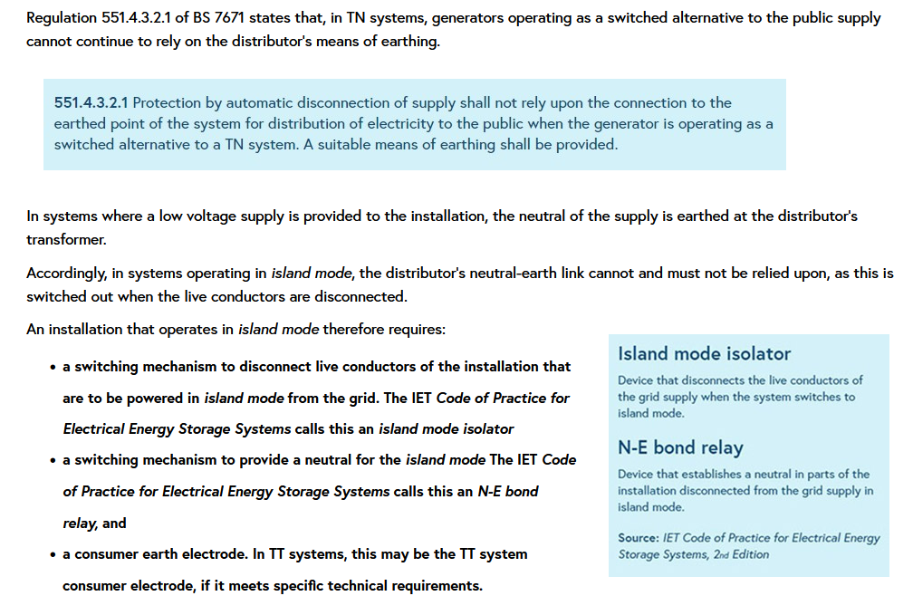
Regulation 551.4.3.2.1 of BS 7671 states that, in TN systems, generators operating as a switched alternative to the public supply cannot continue to rely on the distributor’s means of earthing.”
As I previously mentioned. The earthing needs to be separated so that when you are on the EPS. You are not connected to the grid at all and solely reliant on the EPS supply and your own earth rod.
“Cannot continue to rely on the distributor’s means of earthing” doesn’t mean you have to disconnect / separate the incoming TN-C-S earth - it simply means and additional earthing method with a suitably low resistance should also be connected.
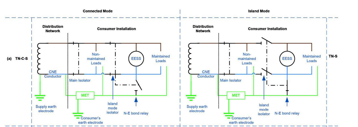
The excerpt shown below mentions that the “Island mode isolator” is a device that disconnects the live conductors of the grid supply - the earth isn’t a live conductor.
The diagram from the same document shown below shows the Consumer’s earth electrode connected to the TN-C-S earth provided by the distribution network - this isn’t switched in the diagram.
Fair enough, I stand corrected. Every days a school day.
If you’re using SWA from the EPS output on the inverter to the change over switch. Then I don’t see why you couldn’t just use an MCB instead of an RCBO if all your circuits are individually RCBO’ed.
To answer my own query & hopefully help other users:
GivEnergy have confirmed via email that my plan to have a suitable 2 pole MCB close to the inverter and then all 2 pole (Line + Neutral) 30mA RCBO’s in my consumer unit is OK with them.
Obviously, anyone going using Method 3 in the GIvEnergy guide needs to be careful not to overload the output from the inverter. My plan is to turn off all RCBO’s in my house consumer unit before changing over and then only turn on alarm / boiler / lighting circuits etc. and leave high power items (cooker etc.) turned off. I’ve got myself a 1000w travel kettle to help reduce the total load.
Hi, I have just come across this topic. We seem to have a possibly similar situation to the one you describe. I am interested when you say it is tripping the RCBO does this actually flip the RCBO off, or does the inverter just restart itself? I ask because when we use our manual changeover switch we are having a lot of problems getting the battery to power the circuits as it just keeps ‘re-starting’. Lights are generally fine but the power circuits are causing us the issue. the Inverter is 11kw and so with all the circuit breakers off I am surprised switching one circuit on will cause this. I wonder if it’s an earth leakage issue?
In my case is was the combined earth leakage over a number of circuits tripping the RCBO. Not similar to what you describe. Sounds like you are taking more load than the inverter can supply. Mine is a Gen 3 Hybrid so limited to around 3Kw unless the sun is shining.