Hi all!
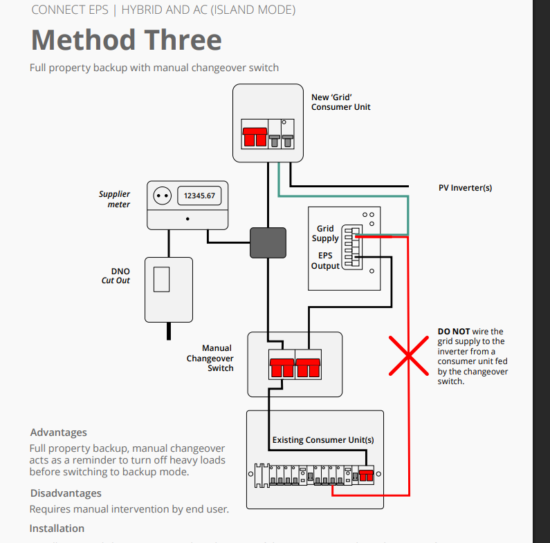
Looking at the wiring diagram for Method 3.
I see that the supply feeding the inverter must not come from the consumer unit on the output of the MTS.
So that means a separate DB supplied from the meter to power the inverter.
my Q.
In the event of grid failure, the power is dead to the meter - I turn the MTS to EPS mode.
what happens when the power from the grid returns/re-energise and it hits the DB supplying the inverter? Am i meant to be turning that DB off too? Or does the inverter recognise the incoming voltage and i can then just turn the MTS back to grid mode?
I have this exact setup myself, and my installer told me that you “Should” change it back straight away… ( once the power is stable )
On page one of the EPS Guide you have, there is a section about NOT overloading the EPS.
it was explained to me that the “New Grid” Consumer unit only has Items wired in that you want protected ( so not the whole house ), I for example have my internet/ Home office and my fridges protected ( Nothing from the Kitchen circuits ie: oven as they draw to much power ), so if the power comes back and you start using these high power items then it “Could” put you inverter into protection mode.
So for me - I manually switch to EPS if power goes out, and then I make sure I unplug anything “High Load” from NON protected circuits so that when the power returns there isn’t a surge in power which could overload the inverter.
I have written some instructions what needs to be done if the power goes out and have them stuck to the EPS switch so that whoever ( the wife ) has to switch to EPS mode knows what to do.
as a side note - make sure you have everything in your system labelled and documented what it does and start-up / shutdown instructions ( as in a few years time of it working without issue you will forget what to do ).
I would also be interested on what other people have done as well.
i think you have it mixed up, the “new grid” is seemingly only inverters / generation related as outlined on the wiring diagram in my first post.
as politely as i can - I didn’t ask about overload or your own procedures. i understand all that.
just curious on what happens when the grid re-energises and thus restores power to the inverter as that will not be isolated from the grid via the manual transfer switch as it will be outside of it.
I have this setup, I have my high load circuits (showers, oven, etc) on one fusebox and my low load circuits (house ring main, lights) on a second fusebox that is wired to the EPS connections on my inverter.
I leave the changeover switch permanently in the inverter position so the inverter EPS terminals are feeding that fusebox all the time.
Internally inside the inverter the EPS terminals are connected to the incoming grid supply when the grid is active, when the grid is lost a relay drops over and the EPS terminals are fed from the battery.
The changeover switch in my case is only ever used if I want to turn the inverter off.
1 Like
So there is no issue with the grid supply being live to the inverter whilst using the EPS output at the same time.
Fair enough, will go with my installation as thought and just separate the inverter supply out of the DB into its own supply.