Solar iBoost - remote control now available in HA

When my GE system was originally installed in 2022, I also had a Marlec Solar iBoost+ installed to intercept any excess solar and divert it to the DHW immersion heater. It’s a bit like the Eddi, but dumb.

As time moved on, I opted for Agile incoming and Fixed Export (15p/kwh) and so export became more valuable than diverting it to the solar. Then, along comes the free energy sessions and negative pricing, which I wanted to capitalise on, and so sought a way of using the iBoost again.

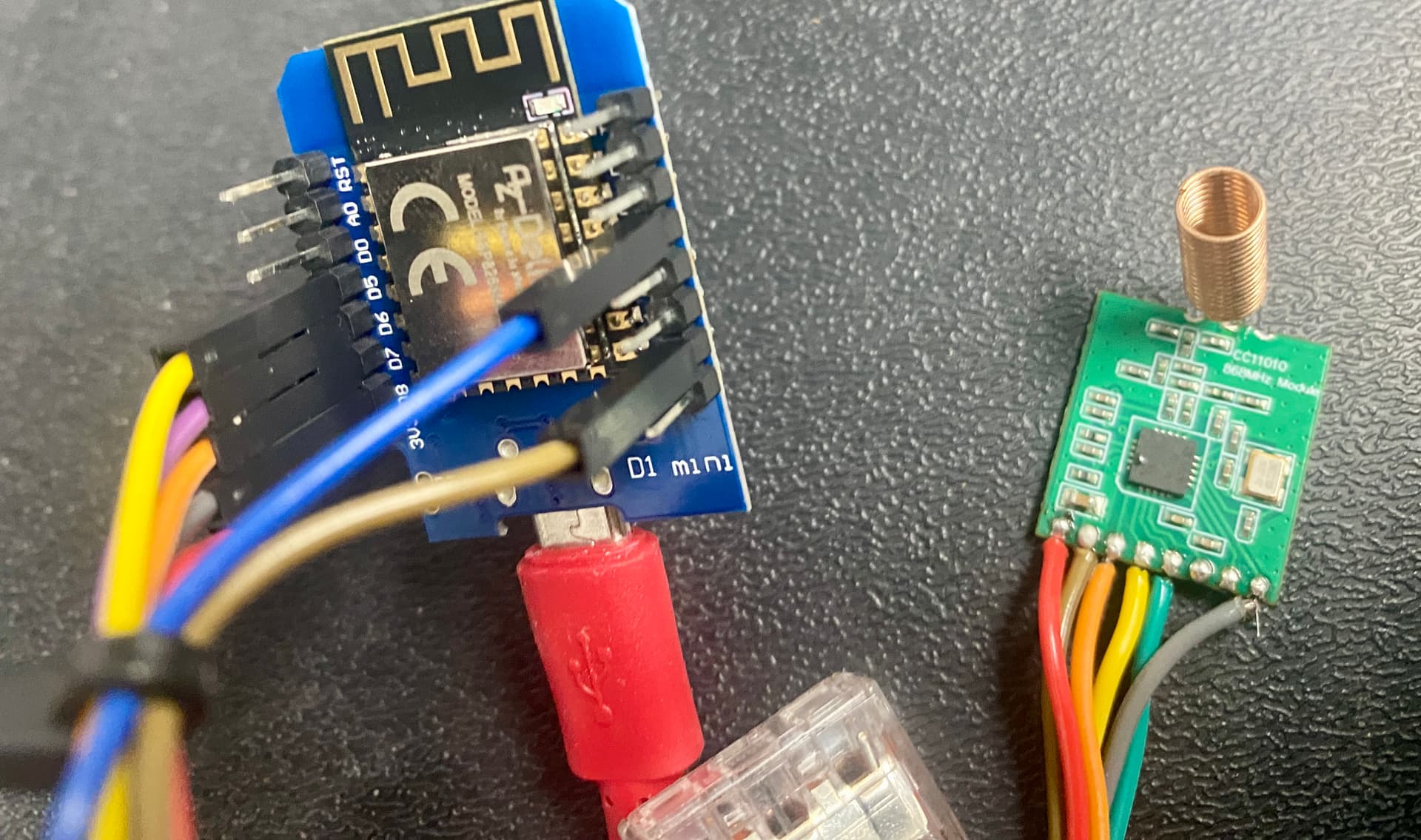
I found a very good solution by JNSwanson, who has decoded the iBoost’s RF signals using an ESP32 and CC1101 868mhz module, providing full remote control and sensor readings into HA. The full project can be found here.

A word of warning here: If you want to try this, save yourself the bother of the cheap, long thin 868 modules, as these often come with no instructions on the pin outs and, if the pins are labelled on the board, they’re often wrong. I found out after trying 4x different boards and almost giving up.

All in all, I spent £8 on an ESP32 D1 Mini and around £8 for the CC1101 module, which is the small square one. You do not need the iBoost Buddy (external screen) for this to work.

Avoid these.

Get this one.

You will need a very small tipped soldering iron, as standard jumper leads are too big, so get the magnifying glass at the ready.

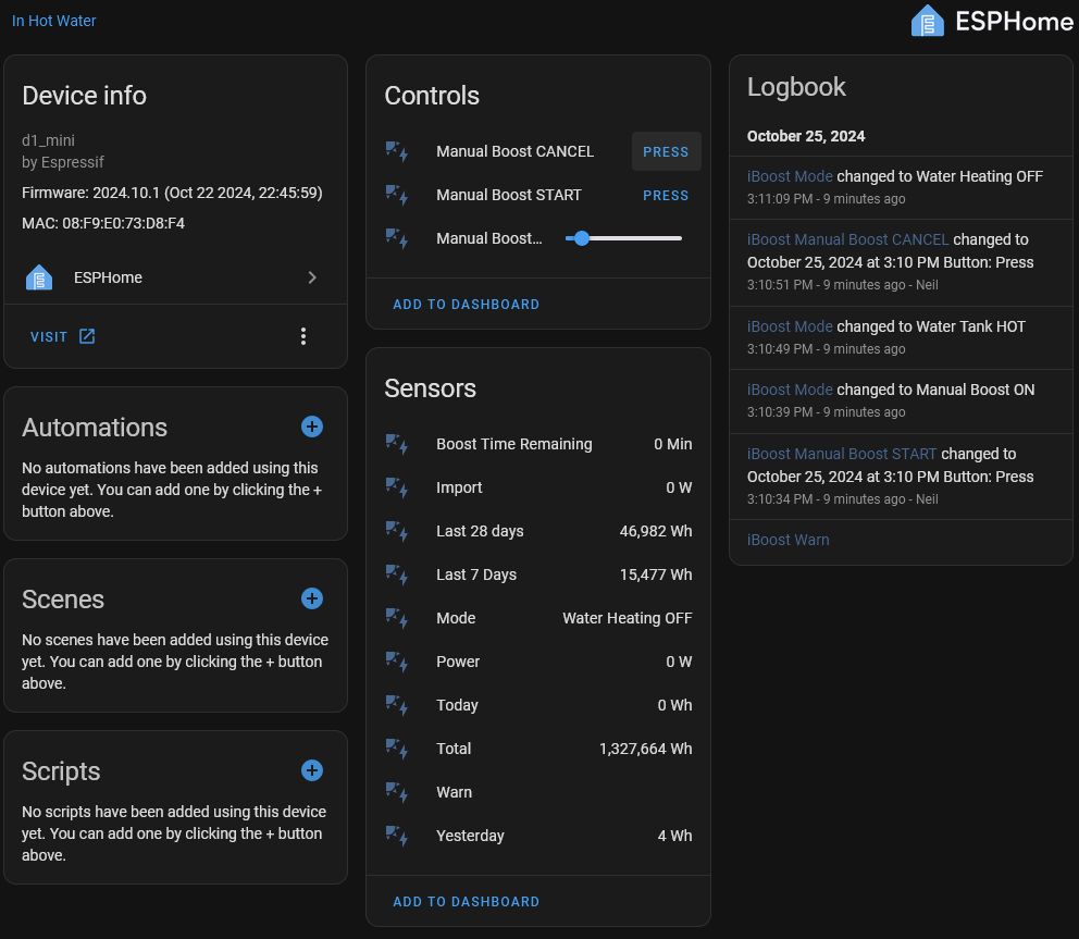
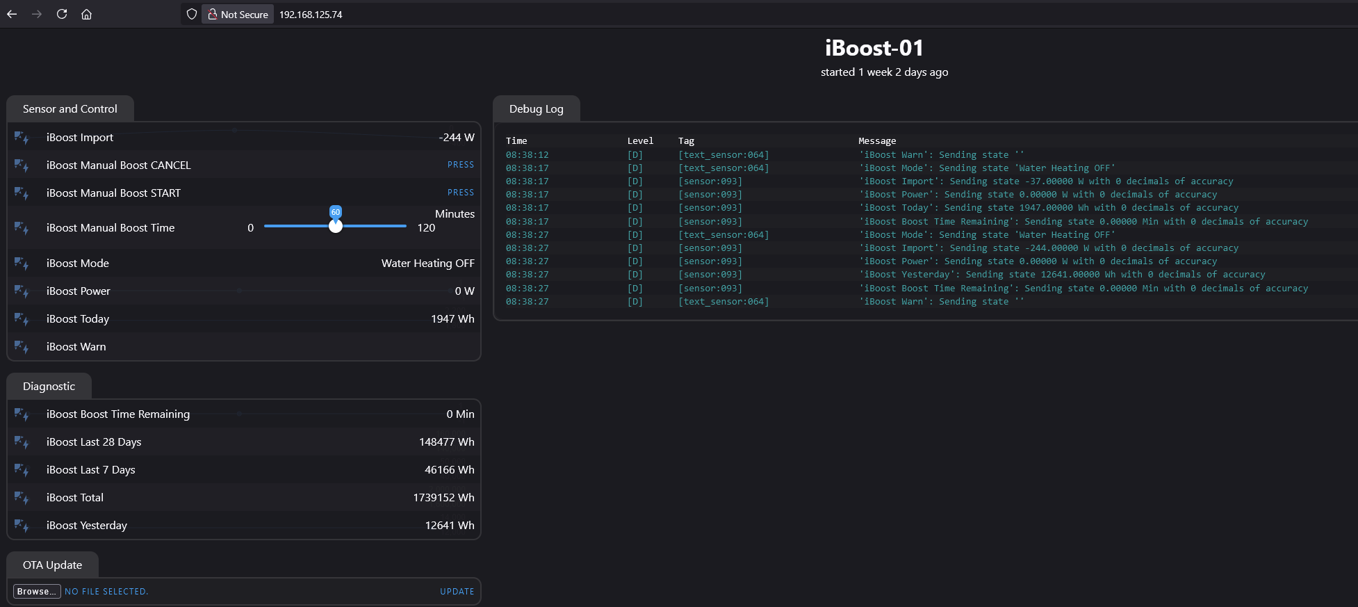
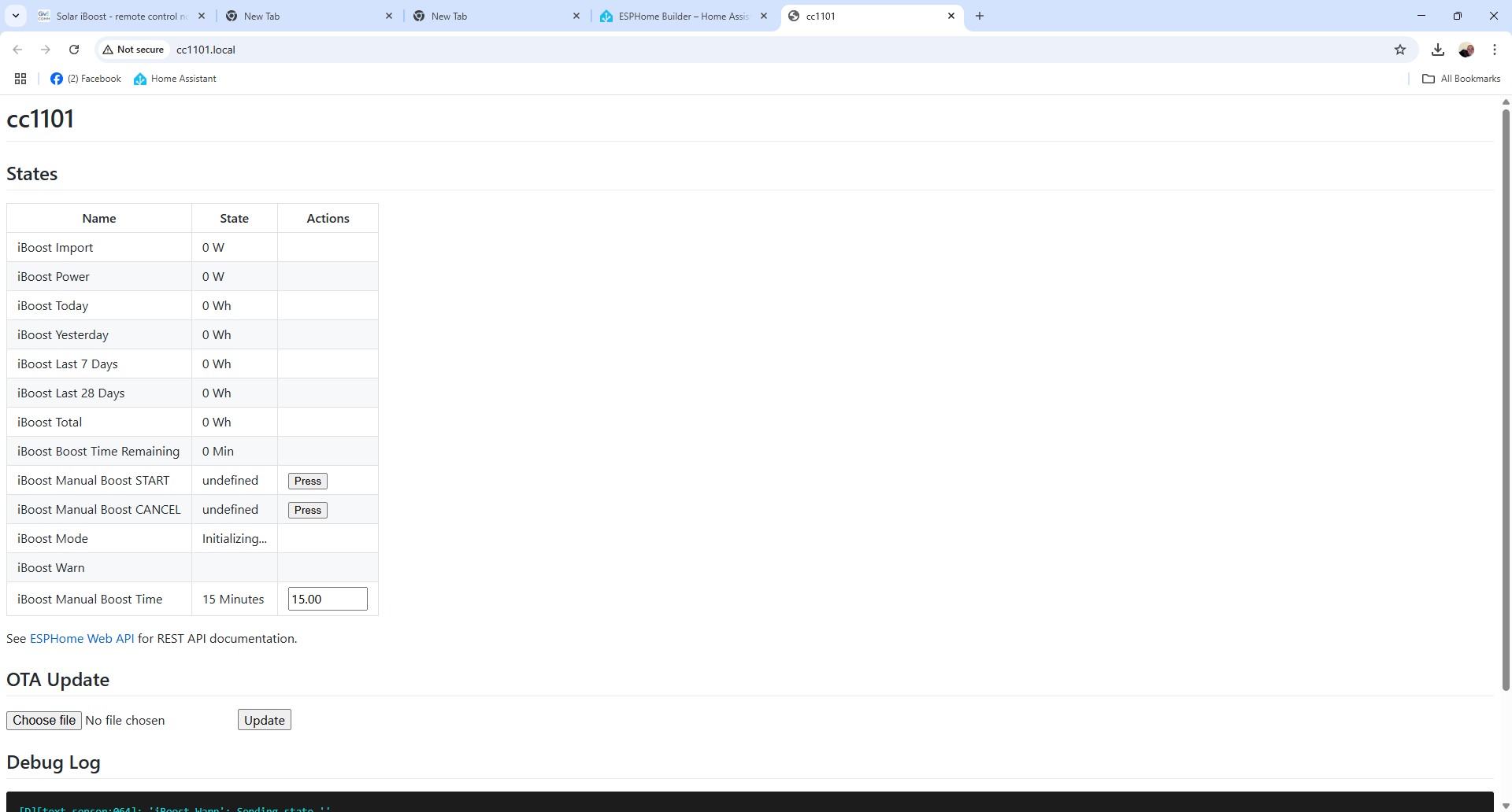
After following the instructions in the Github project and double / triple checking the connections, it simply sprung into life. I now have full control over the iBoost and have simply disconnected the CT clamp, so it no longer intercepts export energy when it feels like it.

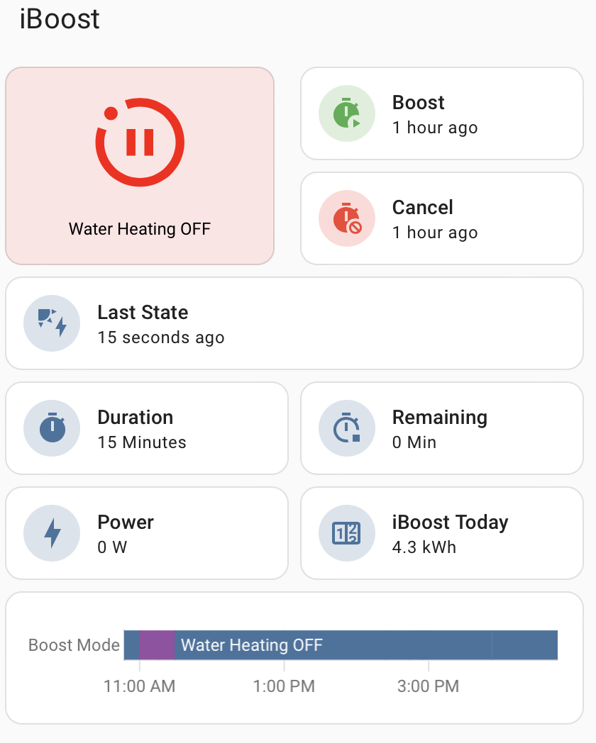
Here’s how I have it showing in HA and I use automations to turn on the iboost for half hour periods to match the cheap energy rates.

Happy to help, if anyone wants to try this for themselves.

2 Likes

Do you have the link for the D1 Mini board as well - or will any ESP32 one work ?

These are the ones I use. I guess you could use any other, but you may need to tweak the YAML for a different board. I just went for the simplest option and used the recommended board.

https://amzn.eu/d/cHVyCZp

Make sure you follow the instructions meticulously, especially the note about moving the source files into a specific folder in ESPHome, otherwise the compile fails and doesn’t find the files.

1 Like

I already have an iBoost - but am thinking to upgrade to the iBoot+

Would I also need to buy the iBuddy - or would this solution replace the need for the iBuddy ?

Hi, sorry for the delay. You do t need the buddy. Unless you want an in home display, but I use Home Assistant for that.

Personally, if you have to upgrade to the plus to get the radio, I’d look at the Eddi instead as it will be far simpler than doing this hack. I’m not sure on the price difference.

iboost+ bought from ebay £120… + the D1 and C1101 for £20 ( and hours of messing about )

But it’s working for me :-)

1 Like

I’ve got this up and running - big thanks to everyone on here…

One question - are you able to set the POWER level that the system uses or is this still being determined from the clamp provided with the iBoost?

I can see the power sensor, but it appears to be a display only.

I was going to link how this is driven from my Shelly Pro 3EM, as I have a 3 phase system, so puting a single clamp doesn’t work for my setup

Thanks

Trevor

No you cannot set the power levels… it’s either based on the information from the CLAMP based on excess energy, or you press the BOOST and it goes at 100% of what the immersion heater can do ( mine it 2.6kw )

I would add to this :slight_smile: - this is NOT using a programming API, this is just a radio signal so it just emulates the iBOOST Buddy - and this is not a feature on the Buddy either.

Actually… if you wanted to get really technical - you could write a script that controls a Forced Battery export, so if you only wanted to use 1KW in the iboost you change the forced export amount.

But this just seems crazy and complex to do.

Thanks for claification - all good

Also I have the following messages which I don’t yet fully understand

Are these assocaited with the iBuddy?

This is the exact output to expect…

But I am not sure what you are integrating it with !!

I used this guide to integrate into Home Assistant : GitHub - JNSwanson/ESP-Home-iBoost: ESPHOME Marlec iboost integration

So when I used ESPHome within Home Assistant + the .yaml file from the github it created the “Sensors” within Home Assistant so that it is then viewable.

The sensors are used to read the data but the .yaml also creates the “Button” within Home Assistant to allow for the Boost feature to be sent.

If you are not using home assistant then the iBoost.h file contains the code on read the output - and also how to send the commands for the BOOST feature.

Hi,

I’m using this within Home Assiatant, and yes I can see similar set of sensors within my Home Assistant environment. The debug log was from the code compile and download process. Once the system had downloaded the code to the ESP8266 board and started executing the code, this was the displayed debug data being reported to the terminal window (cmd).

It appears to be working, but I like to understand error/warning messages when possible

So when I see Component messages, I was just interested in why, and if there is some issue with my installation.

Well - I just tried looking at my logs - but now can’t as ESPHOME has been updated and the iBOOT.yaml and code no longer work !!!

It’s still working in HomeAssistant - but I can no longer interact with ESPHOME !!!

Hopefully someone will fix the code as it seems the code is now using depreciated features.